Dwyfor Tech Pas-Isel construction
PermalinkThe Pas-Isel low-pass filter is the first Eurorack module designed by Dwyfor Tech. It is sold as either a full DIY kit, or just the PCB and front panel. I bought the basic self-source set, considering that I already had most of the parts to build it in stock. It is designed mostly with very common parts, which make the DIY option affordable for anyone who has been accumulating tubes of TL074 op-amps over time.
Sourcing the materials
The original bill of materials indicates part numbers for Mouser and Thonk. However, when I purchase from those vendors, the package goes across borders. That leads to longer delivery times and that usually triggers significant duty charges. On the other hand, I'm confident that I can source most parts from Digi-Key, who offer free shipping with all duties paid. The Alpha potentiometers and trimmers still need to be purchased from Thonk as no alternatives are available.
Equivalences and substitutions
Every metal film resistor has been replaced from parts with a 600 mW power rating to 250 mW. The resistors that need to carry more current are probably the voltage dividers on the control board, and those will never have to dissipate over 100 mW. The 250 mW (often referred to as 1/4 W) have been much more common in my past projects.
The attributes of the 22 pF ceramic capacitor were not specified, but anything with a C0G temperature coefficient and 5 mm between leads seemed
like an appropriate choice. I used whatever I had in stock for the 100 nF decoupling capacitors. However, the exact part number has been lost long ago.
The 1 nF film capacitors I had in stock were the classic AVX yellow boxes. I still have those in large quantity for a wide range of values. I'm glad I can get some to be used in a project. However, they are now obsolete and have been replaced by equivalent parts from EPCOS. I have specified those replacements in the bill of materials below.
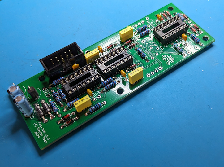
The power header has been replaced by a keyed shrouded header. It barely touches the yellow box capacitor next to it. This is the part I already had in stock, so there was no reason to source a non-keyed header. Be aware that this might increase the required depth of the module.
The 1N5819 Schottky diode have been replaced by 1N5818. The reverse voltage is 30 V instead of 40 V, which will still allow adequate protection. I used whatever ferrite beads I had in stock, which is now obsolete and unavailable. I would suggest looking for other, potentially more appropriate options.
At the time of placing the order at Thonk for the potentiometers, the 100 kΩ trimmer potentiometers went out of stock. Synthcube didn't have any left in stock, either. Other places would sell them, but at ridiculous prices when delivery was added to the price. After having shared my frustration on the Winterbloom discord server, we agreed that the 50 kΩ potentiometer would probably play the role correctly.
On the audio jacks, I mounted hex instead of knurled nuts.
I strongly do not recommend substituting the TL074 op-amp ICs with SM74HC04. For some reason, they do not handle 24 V between some pins very well. This is what happens when a tube has been placed in the wrong anti-static back (maybe 15 years ago), I'm sick, and my brain is foggy. Again, strongly not recommended.
Bill of materials
Heavily influenced by the Winterbloom Helium self-source guide, here's an alternative bill of materials for Pas-Isel:
Main board
| Reference | Value & Rating | Qty | Part no | Digi-Key |
|---|---|---|---|---|
| C1, C2 | 10µF 35V/±20% | 2 | Panasonic ECE-A1VKS100 | P980-ND |
| C3, C4, C6, C7, C9, C10 | 100nF 50V/±5%/X7R | 6 | various | |
| C5, C11, C13, C15 | 22pF 50V/±5%/C0G | 4 | Vishay K220J10C0GF5UH5 | BC5230CT-ND |
| C8, C12, C14, C16 | 1n 63V/±5% | 4 | EPCOS B32529C0102J000 | 495-10910ND |
| R1, R3, R10, R12 | 47kΩ 250mW/±1% | 4 | Yageo MFR-25FTE52-47K | 13-MFR-25FTE52-47KCT-ND |
| R2 | 10kΩ 250mW/±1% | 1 | Yageo MFR-25FTE52-10K | 13-MFR-25FTE52-10KCT-ND |
| R4, R8, R13, R17 | 2.2kΩ 250mW/±1% | 4 | Yageo MFR-25FTE52-2K2 | 13-MFR-25FTE52-2K2CT-ND |
| R5-R7, R9, R11, R15, R16, R18 | 100kΩ 250mW/±1% | 8 | Yageo MFR-25FTE52-100K | 13-MFR-25FTE52-100KCT-ND |
| R14 | 150kΩ 250mW/±1% | 1 | Yageo MFR-25FTE52-150K | 13-MFR-25FTE52-150KCT-ND |
| FB1, FB2 | - | 2 | Murata BL01RN1A1F1J | 490-10999-2-ND |
| D1, D2 | Schottky 30V/1A | 2 | Vishay 1N5818-E3/73 | 112-1N5818-E3/73CT-ND |
| D3-D16 | 1N4148 | 14 | MCC 1N4148-TP | 1N4148-TPMSTR-ND |
| U1-U3 | TL074 | 3 | TI TL074IN | 296-7200-5-ND |
| J1, J3 | 1x4 2.54 Header | 2 | Samtec TLW10405TS | SAM1099-04-ND |
| J2 | 2x5 2.54mm IDC Header | 1 | Würth 61201021621 | 732-2094-ND |
| RV1 | 100kΩ 25-turn Trimmer | 1 | Bourns 3266W-1-104 | 3266W-104-ND |
Control board
| Reference | Value & Rating | Qty | Part no | Digi-Key |
|---|---|---|---|---|
| C1, C2 | 1µF 63V/±5% | 2 | EPCOS B32529C0105J0000 | 495-1119-ND |
| R1, R2 | 150kΩ 250mW/±1% | 2 | Yageo MFR-25FTE52-150K | 13-MFR-25FTE52-150KCT-ND |
| R3, R5 | 100kΩ 250mW/±1% | 2 | Yageo MFR-25FTE52-100K | 13-MFR-25FTE52-100KCT-ND |
| R4 | 68kΩ 250mW/±1% | 1 | Yageo MFR-25FTE52-68K | 13-MFR-25FTE52-68KCT-ND |
| R6 | 22kΩ 250mW/±1% | 1 | Yageo MFR-25FTE52-22K | 13-MFR-25FTE52-22KCT-ND |
| R7 | 200kΩ 250mW/±1% | 1 | Yageo MFR-25FTE52-200K | 13-MFR-25FTE52-200KCT-ND |
| R8 | 47kΩ 250mW/±1% | 4 | Yageo MFR-25FTE52-47K | 13-MFR-25FTE52-47KCT-ND |
| J1-J3, J5 | Audio jack | 4 | WQP-PJ398SM | Available from Thonk |
| J4, J6 | 1x4 2.54mm Receptacle | 2 | Samtec SLW1040TS | SAM1093-04-ND |
| RV1, RV2 | 50kΩ/Linear Trimmer potentiometer | 2 | Song Huiei R0904-B50K,L-25KQ | Available from Thonk |
| RV3, RV4 | 100kΩ/Linear Potentiometer | 2 | Alpha RD901F-40-15R1-B100K | Available from Thonk |
| RV5 | 100kΩ 25-turn Trimmer | 1 | Bourns 3296W-1-104 | 3296W-104-ND |
Assembly hardware
| Description | Qty | Part no | Digi-Key |
|---|---|---|---|
| M3 0.250" Standoff | 5 | Essentra MTS-6 | RPC4428-ND |
| M3 Screw | 10 | Würth 97790403111 | 732-13702-ND |
Building the module
After reading all the steps from the build guide, I assumed it was safe to solder every passive component on both boards first, then thoroughly clean up all the water-soluble flux. I could then solder the potentiometers and jacks with no-clean solder, and finally inserting the ICs into the sockets.
Instead of using the excellent rubber band method for assembling the panel components, I screwed hex nuts on the potentiometers and some audio jacks. It works just as well because the board connectors are solid enough to prevent the PCBs and front panel from separating.
Final steps
My test setup has everything I need to power up a single module easily with Winterbloom Micronova Eurorack power supply and a Joranalogue Test 3 module. The initial test and the calibration procedure turned out to be tricky to perform because I'm not prepared to hook a signal from an output jack into the oscilloscope. A couple test points would have certainly helped here. I cut a Cre8audio cable (sorry, they're just not great) open and attached the oscilloscope probe to the wires. I yet have to calibrate the V/oct pitch control, but that shouldn't be too difficult if I patch it from a Mutant Brain.